CNC Machining
CNC Machining – Making Weight Moulds
Casting shapes such as those for soft plastic lures is fine when pouring the molten plastic onto the RTV silicone, but when it comes to pouring molten lead into such as sinker moulds then that’s another problem, the mould needs to be more heat resistant, usually aluminium alloy. Of course this means that the previous method of casting against a master goes out the window. We now need to actually cut or machine the aluminium to achieve the cavity shape.
To do this we need to use a machine capable of lots of small controlled movements - A CNC machine. CNC stands for Computerized Numerical Control.
This allows the user to create an NC (Numerical Control) program that will bit by bit fire numbers (actually controlled pulses) to the machine and cause it to move 1,2 or all 3 of its axes.
In reality there are many more complex machines with more than 3 axes but for simplicity I have kept this report to the basic three axes. Ie X – right to left, Y – forward and back and Z -up and down. These 3 axes cover a 3D volume so enable the machine by commanding X,Y or Z to move a cutting tool to anywhere within the workspace volume.
The subject matter on CNC machining is vast and covers many thousands of web pages if searched for but for simplicity what follows is my own account.
Firstly, to maintain interest, lets start with a picture of the end result .......
Firstly, to maintain interest, lets start with a picture of the end result .......
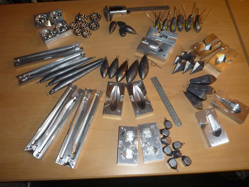

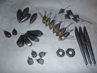
I’m sure many have seen and used fishing weight moulds to make your own weights, it’s not such a big deal but designing your own and machining it adds another dimension to the satisfaction stakes. And there is the added bonus that you can do almost anything with it, I personalize my moulds with the boat name engraved into the cavity. I’m sure it don’t catch more fish but it certainly looks good.
To achieve the end result there are three main stages to go through :-
To achieve the end result there are three main stages to go through :-
1. The Design
2. The Programming 3. The machining

Firstly the Design ........
For this you will need a CAD (Computer Aided Design) package There are many on the market ranging from “F ree Download” to awfully expensive commercial packages ....... So try some of the free to downloads and see what your most comfortable with. I use a 3D package which affords me the ability to create a variety of 3D shapes and surfaces, unfortunately the choice is so vast I could not recommend any,.... other than download one, try it, and see how it goes. After some practice you should be able to design your mould similar to that shown. For size I usually do some basic calculations regarding the density of lead (although some of the more expensive packages can do this for you) then, after the first cast I weigh the result and modify the design to suit. Remember at this stage you need to prepare some method of locating the 2 halfs together and also you need a means of getting the lead in the mould (a hole called a spru) I also add pockets to enable opening of a hot mould and a few vents to make it better to fill – oh and of course a means of locating the loop. And of course don’t forget you also need a mirror image for the second half ... So after a few hours or maybe days painstaking work, here’s one of my designs .........
For this you will need a CAD (Computer Aided Design) package There are many on the market ranging from “F ree Download” to awfully expensive commercial packages ....... So try some of the free to downloads and see what your most comfortable with. I use a 3D package which affords me the ability to create a variety of 3D shapes and surfaces, unfortunately the choice is so vast I could not recommend any,.... other than download one, try it, and see how it goes. After some practice you should be able to design your mould similar to that shown. For size I usually do some basic calculations regarding the density of lead (although some of the more expensive packages can do this for you) then, after the first cast I weigh the result and modify the design to suit. Remember at this stage you need to prepare some method of locating the 2 halfs together and also you need a means of getting the lead in the mould (a hole called a spru) I also add pockets to enable opening of a hot mould and a few vents to make it better to fill – oh and of course a means of locating the loop. And of course don’t forget you also need a mirror image for the second half ... So after a few hours or maybe days painstaking work, here’s one of my designs .........

Next the Programming ..........
For this you will need a CAM (Computer Aided Manufacturing) package, again similar to the CAD package there are a number around from free download to very expensive, often linked with the previous to become CAD/CAM Packages.
To use this you will need lots of practise, too much to go into here but just to explain the CAM package allows you to add “toolpaths” (the path you want a particular tool to take) and follow the Geometry you have created in the Design. (I have a little help here in that this is what I have been doing 8 hrs a day for the past 40 years)
To use this you will need lots of practise, too much to go into here but just to explain the CAM package allows you to add “toolpaths” (the path you want a particular tool to take) and follow the Geometry you have created in the Design. (I have a little help here in that this is what I have been doing 8 hrs a day for the past 40 years)

When you are happy with the results of the programming then the toolpaths are output (or “posted”) to a text file that the machine controller can use. This is “Man Readable Text” but usually very vast in size and difficult to understand. It is basically a line by line list of X,Y and Z Co-ordinates that you want the Tool in the machine to follow ......
Something Like this .................................
%
O0860 (VERSION - 2 DATE PRODUCED - 22 JUL 15}
N2 ( SAMPLE PART )
N4 G90 G94 G17 G00 G40 G80 G49
N6 G54
N8 G21
N10 M31
N12 M32
N14 M33
N16 G5.1 Q0
N18 M05
N20 M09
N22 G91 G28 A.001 B.001 Z.001
N24 G91 G28 G49 A0 B0 Z0
/N26 T12
/N28 G91 G30 X.001 Y.001 Z.001
/N30 G91 G30 X0 Y0 Z0
N32 (TOOL 12 LENGTH 0.)
N34 M05
N36 M19
/N38 M6
/N40 G91 G0 X750.
N42 M0
N44 (***** TOOL CHANGE T12 *****)
N46 M1
N48 G5.1 Q1
N50 G90 S10000 M3
N52 G0 X533.239 Y-219.
N54 A0. B0.
N56 G90 G0 G43 H12 Z100. F1000 M08
N58 Z24. A0. B0.
.
N60 G1 Z10.5
N62 Y-198.34 F2500
N64 G3 X523.239 Y-188.34 I-10. J0.
N66 G1 X277.728
N68 G3 X267.728 Y-198.34 I0. J-10.
N70 G1 Y-219.
N72 G0 Z100. A0. B0.
N74 X533.239 Y-219.
N76 Z15.5 A0. B0.
N78 G1 Z2. F1000
N80 Y-198.34 F2500
N82 G3 X523.239 Y-188.34 I-10. J0.
N84 G1 X277.728
N86 G3 X267.728 Y-198.34 I0. J-10.
N88 G1 Y-219.
N90 G0 Z100. A0. B0.
N92 X267.728 Y2.249
N94 Z24. A0. B0.
N96 G1 Z10.5 F1000
N98 Y-9.439 F2500
N100 G3 X277.728 Y-19.439 I10. J0.
N102 G1 X522.581
N104 G3 X532.581 Y-9.439 I0. J10.
N106 G1 Y9.439
N108 G3 X522.581 Y19.439 I-10. J0.
N110 G1 X277.728
N112 G3 X267.728 Y9.439 I0. J-10.
N114 G1 Y2.249
N116 Z2. F1000
N118 Y-9.439 F2500
N120 G3 X277.728 Y-19.439 I10. J0.
N122 G1 X522.581
N124 G3 X532.581 Y-9.439 I0. J10.
N126 G1 Y9.439
N128 G3 X522.581 Y19.439 I-10. J0.
N130 G1 X277.728
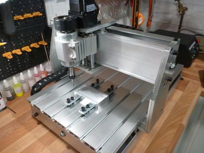
Finally the machining
CNC Machines vary from thousands to many thousands of £’s each but recently there is an influx of small “cheap” desktop CNC Routers on the market mainly from the far east.
These are basically meant for engraving but with a bit of ingenuity and careful programming they can be used for lots more .......
The machine controller software reads the Text NC Program that you have just created and
line by line takes the co-ordinates and converts them into perfectly counted and timed pulses for the X, Y an Z motors to be driven on the Machine.
On my machine each pulse moves the relative axis 0.0125 mm (one eightieth of a mm) therefore a change in co ordinate from one program line to the next program line of say 10mm will cause the software to output 10 X 80 therefore 800 pulses (interactively with other axes to create straight line or curved movements) before moving on to execute the next line in program.
Although both very technical in their own fields the machine and the controller software care nothing at all for each other. The controller reads the program and decides what to do next, if it wants to move say 10mm on one of the axes then it sends 800 pulses timed to perfection (the timing is controlled by the feedrate, the F in the program), if the machine misses any pulses then the controller does not care and moves to the next step regardless. As for the machine it cares nothing about the controlling software or the timing but every time it gets a pulse it converts it to a larger value and pushes it out to the stepper motor in a plus or minus direction uncaring where its been or where its going, it then sits awaiting the next pulse irrespective and unconcerned of the “Program”.
This all happens at amazing speed and individual pulses are rarely seen but they all come together to move the tool along the many toolpaths created in the CAM software package.
There are more industrialised CNC machines that work on servo motors that have their own encoders to feedback to the controller the actual position at any point in time for error checking but not in the small hobby machines, these just carry on regardless converting pulses to movements ..............
Of course there are other little refinements to make such as the location posts ....
These are 2 pins that are a snug push fit in one half and a clearance fit in the other allowing the two halves to be located “exactly” together. This gives a clean join to the mould something that can be done especially well in a machined and more so a CNC machined mould rather than a cast mould. Also the cuts for the wire loop along with a pocket to support the loop whilst assembling the two halves, this can be a real finger burning experience as its difficult to insert the wire wearing gloves and hot without, so any help on support here is a bonus.
All in all a CNC produced mould is exceptionally higher in quality than a traditional cast product but the work content to achieve it is vastly increased accordingly .......
but the satisfaction on completion ....... well that’s just priceless ..
Feedback or Questions
Article To Be completed ...............................